15 Results
View results:
Sort by:

For the stability verification of members using the equivalent member method, it is necessary to define effective or lateral-torsional buckling lengths in order to determine a critical load for stability failure. In this article an RFEM 6-specific function is presented, by which you can assign an eccentricity to the nodal supports and thus influence the determination of the critical bending moment considered in the stability analysis.

You can model and analyze masonry structures in RFEM 6 with the Masonry Design add-on that employs the finite element method for the design. Complex masonry structures can be modeled, and static and dynamic analysis can be performed, given that a nonlinear material model is implemented in the program to display the load-bearing behavior of masonry and the different failure mechanisms. You can enter and model masonry structures directly in RFEM 6 and combine the masonry material model with all common RFEM add-ons. In other words, you can design entire building models in connection with masonry.

In order to create a surface model with failing supports close to reality, an option called "Failure if contact perpendicular to surfaces failed" is available in RFEM 5 for contact solids under "Contact Parallel to Surfaces".

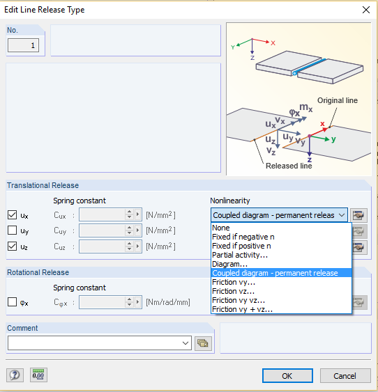
Supports contributing to a load reduction only under compression or tension can be defined as nonlinear supports in RFEM and RSTAB. It is not always easy for the user to select the correct nonlinearity for "failure under tension" or "failure under compression".

With the orthotropic elastic-plastic material model, you can calculate solids with plastic material properties in RFEM 5 and evaluate them according to the Tsai‑Wu failure criterion. The Tsai-Wu criterion is named for Stephen W. Tsai and Edward M. Wu, who published it in 1971 for plane stress states.
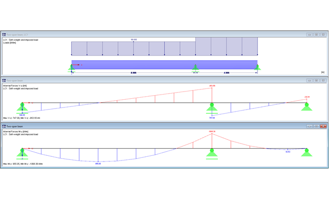
The following article describes designing a two-span beam subjected to bending by means of the RF-/STEEL EC3 add-on module according to EN 1993-1-1. The global stability failure will be excluded due to sufficient stabilizing measures.
The cross-section class of a two-span beam will be designed in the following text. In addition, the necessary cross-section designs will be performed. The global stability failure will be excluded due to sufficient stabilizing measures.

The secondary reinforcement according to DIN EN 1992-1-1 9.2.1 is used to ensure the desired structural behavior. It should avoid failure without prior notification. The minimum reinforcement has to be arranged independently of the size of the actual loading.
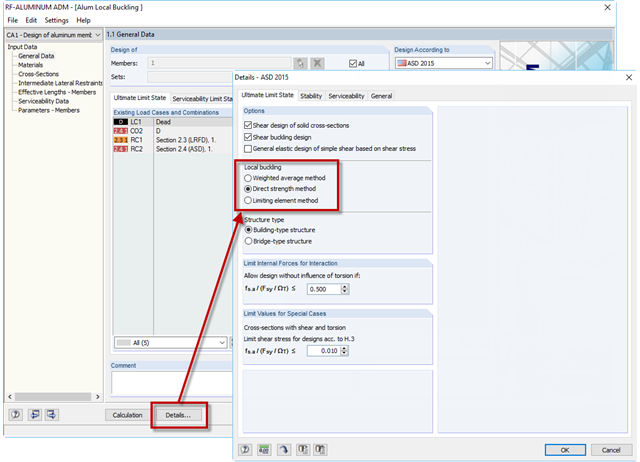
If an aluminum member section is comprised of slender elements, failure can occur due to the local buckling of the flanges or webs before the member can reach full strength. In the add-on module RF-/ALUMINUM ADM, there are now three options for determining the nominal flexural strength for the limit state of local buckling, Mnlb, from Section F.3 in the 2015 Aluminum Design Manual. The three options include sections F.3.1 Weighted Average Method, F.3.2 Direct Strength Method, and F.3.3 Limiting Element Method.
In the case of a post-critical failure, a substantial change occurs in the geometry of a structure. After reaching the instability of the equilibrium, a stable, strength position is reached again. The post-critical analysis requires an experimental approach. It is necessary to manually load the structure in increments step by step.
If a bending load of a brittle beam element (an unreinforced concrete beam) is increased by means of the bending capacity, the structure responds by breaking the cross-section and the member is separated into two segments. At the time of the failure, the broken part suddenly loses its potential to transfer the bending moment. Due to the segmentation, the critical part also fails to transfer the other force types, such as axial forces.
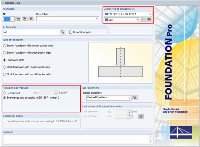
In addition to the reinforced concrete design according to EN 1992‑1‑1, RF-/FOUNDATION Pro allows you to perform geotechnical designs according to EN 1997‑1. In RF-/FOUNDATION Pro, the design of the allowable soil pressure is performed as a ground failure resistance design. If you select CEN as National Annex, you have two options for defining the ground failure resistance. First, you can directly specify the allowable characteristic value of the soil pressure σRk. Second, there is also the option to analytically determine the bearing capacity according to [1], Annex D.
Pushover analysis is a nonlinear structural calculation for seismic analysis of structures. The load pattern is inferred from the dynamic calculation of equivalent loads. These loads are increased incrementally until global failure of the structure occurs. The nonlinear behaviour of a building is usually represented by using plastic hinges.
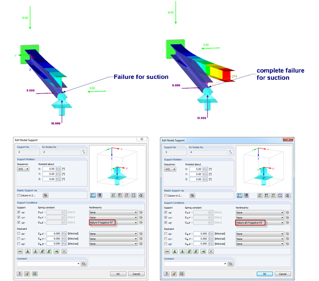
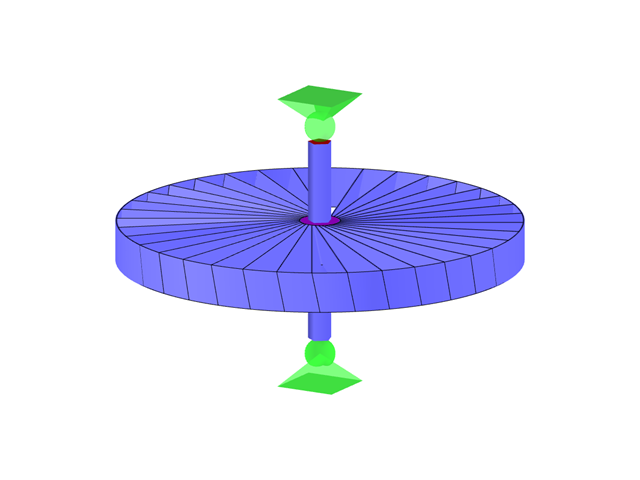
If nodal supports should have an effect in certain directions only, you can define failure. Here is an example of a single‑span beam, of which the right support can only absorb positive vertical loads. The load comprise vertical suction load and horizontal load. However, there are 2 failure options:
1) Failure if negative PZ'
2) Failure all if negative PZ'
The difference is illustrated in the graphic.
1) Failure if negative PZ'
2) Failure all if negative PZ'
The difference is illustrated in the graphic.
If you want to simulate, for example, the failure of particular structural members, you can use the "Modify stiffness" function.